ESD Mats (Anti-Static Mats): Two-Layer Rubber Mats with Measured Test Data
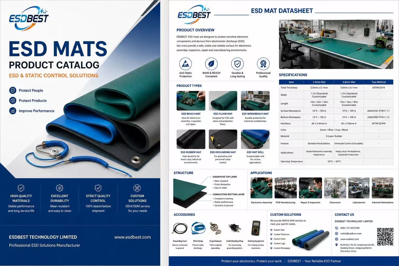
An ESD mat is a grounded work or floor surface that drains static charge from people, tools and electronic parts in a controlled way. ESDBEST makes two-layer rubber ESD mats, also sold as anti-static mats or anti-static matting, in rolls, sheets and custom-cut sizes. This page explains how they work, how they differ from mats labelled only "anti-static", and what our own mats measured on a calibrated meter.
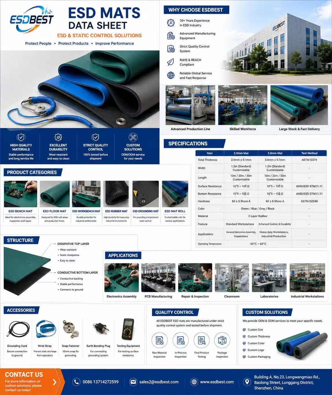
- Construction: two-layer rubber, static-dissipative top layer, conductive bottom layer
- Thickness: 2.0 mm or 3.0 mm (± 0.1 mm)
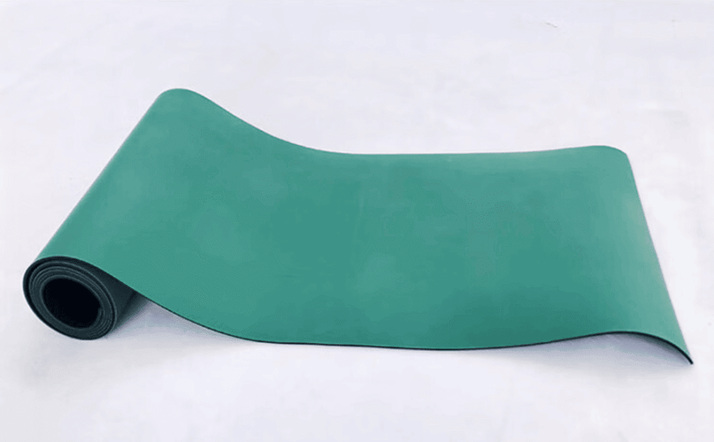
- Roll size: 1.2 m wide (standard) × 10 m, 20 m or 30 m; other widths, lengths and cut sizes on request
- Resistance (design range): top surface 106–109 Ω, bottom layer 104–106 Ω
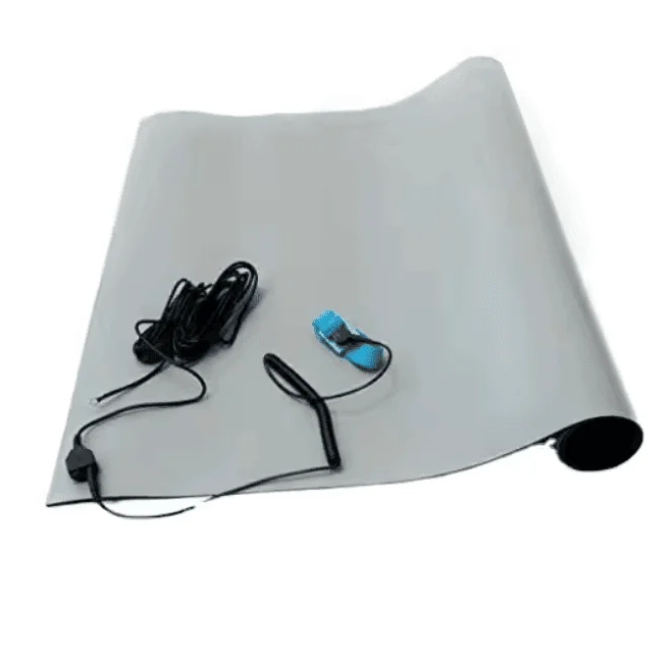
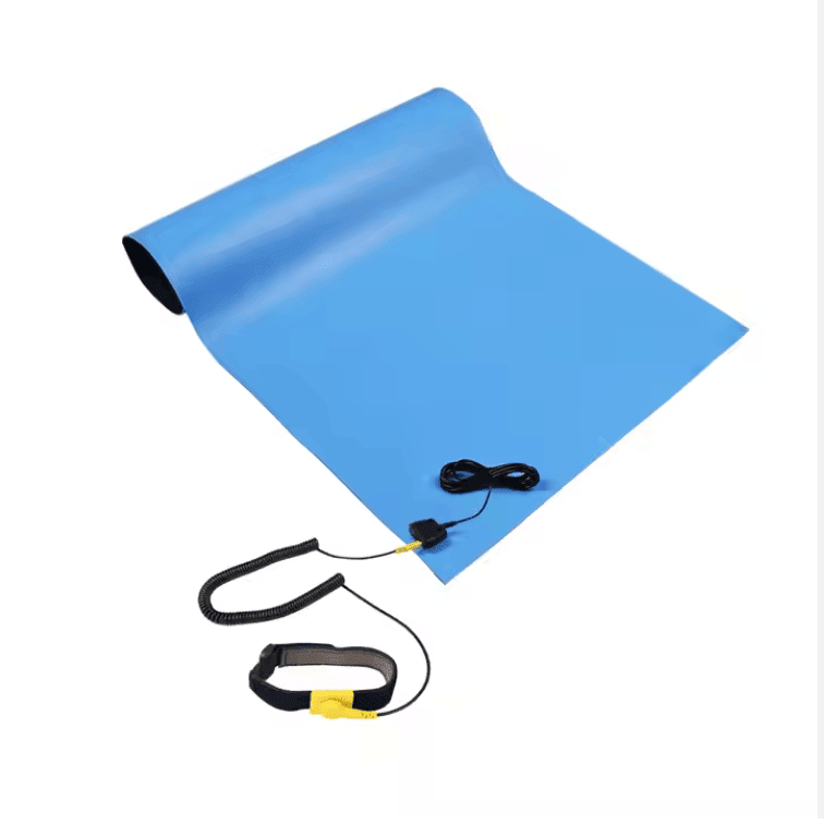
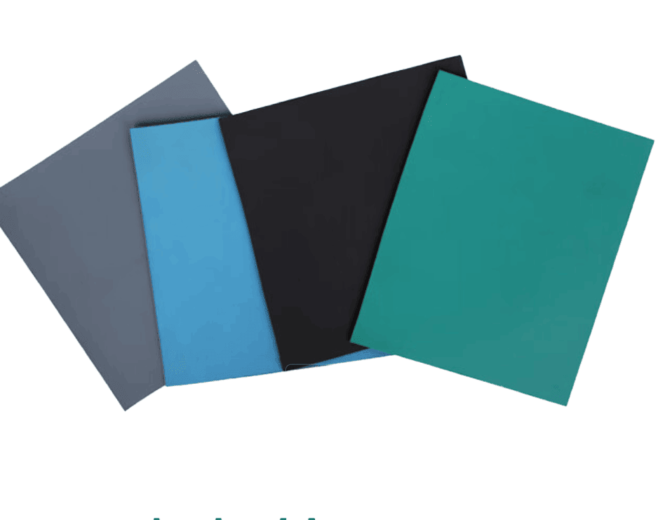
- Colours: green, blue, grey, black
- Measured on our ACL Model 800: resistance to ground 1.64 × 10⁷ to 2.46 × 10⁷ Ω, well under the 1 × 10⁹ Ω limit in ANSI/ESD S20.20
What Is an ESD Mat?
An ESD mat (electrostatic discharge mat) is a resistive surface that is connected to ground. When a charged board, tool or person touches it, the charge flows away through the mat and its ground cord instead of jumping as a spark into a sensitive component.
The key word is controlled. A bare metal bench would also remove charge, but so fast that the discharge itself can damage parts. An insulating bench top does not remove charge at all. An ESD mat sits between the two: low enough in resistance to drain charge to ground, high enough to slow the current down.
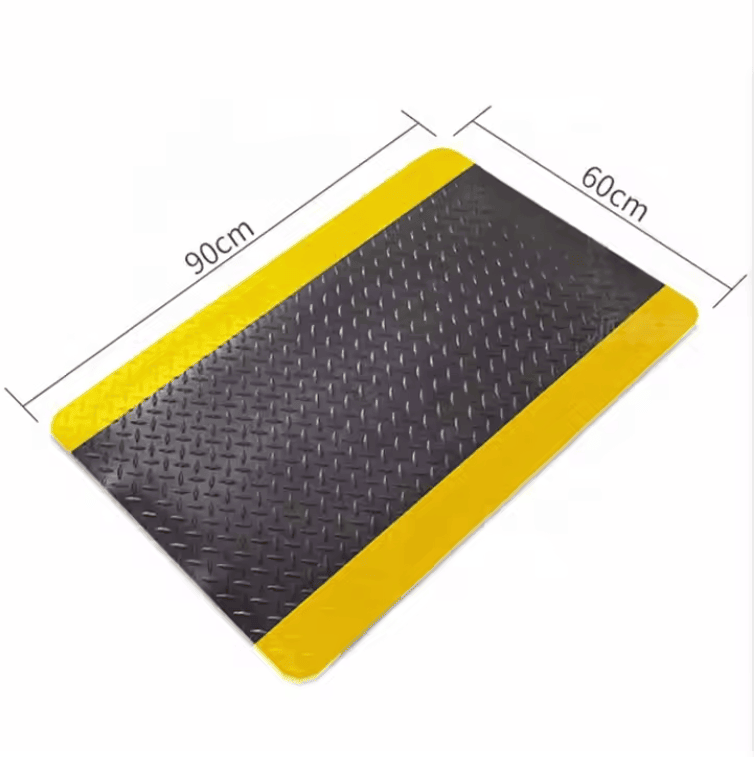
ESD mats are used on electronics assembly benches, repair and rework stations, test and inspection areas, laboratories and in front of production lines. On a workbench they are called ESD bench mats or table mats; on the floor, ESD floor mats.
ESD Mat vs Anti-Static Mat: What Is the Difference?
In everyday use, "ESD mat" and "anti-static mat" are often used for the same product, and many suppliers, including us, use both names. The difference that matters is not the name on the label but what the mat does electrically.
| ESD mat (grounded, resistance-controlled) | Mat sold only as "anti-static" | |
|---|---|---|
| Main job | Drains charge to ground at a controlled rate | Reduces how much static is generated on its surface |
| Ground connection | Yes: snap and ground cord to a common ground point | Often none |
| Resistance specified | Yes, point to point and resistance to ground | Often not stated |
| Fits an ANSI/ESD S20.20 programme | Yes, if it measures below 1 × 10⁹ Ω point to point and to ground | Only if it is tested and meets the same limits |
| Typical use | Electronics assembly, repair, test, labs | Packing tables, general workplaces |
"Anti-static" describes low charge generation. It is not a resistance class. A mat that does not charge easily can still be too insulating to drain charge, and a mat with no ground connection cannot drain charge anywhere. So when you compare mats, ask for two numbers: resistance point to point and resistance to ground, measured to ANSI/ESD S4.1. Our results are below.
How Do ESD Mats Work?
A two-layer ESD mat uses two rubber compounds with different jobs:
- Top layer, static dissipative (106–109 Ω). This is the surface where parts are placed. Its resistance slows the discharge so that a charged device does not release its charge all at once.
- Bottom layer, conductive (104–106 Ω). This layer spreads the charge sideways across the whole mat to the ground snap.
The path to ground is: part or tool → through the dissipative top layer (once, where it touches) → along the conductive bottom layer → ground snap → ground cord → common ground point. Because the bottom layer is so much more conductive, it hardly matters how far from the snap a part is placed.
Our own measurements show this. On a 320 × 320 mm sample, resistance to ground was 2.31 × 10⁷ Ω at the corner farthest from the snap and 2.46 × 10⁷ Ω at another corner, a spread of about 6 %. On a single-layer mat, resistance to ground rises much more with distance.
A mat only works when it is grounded. A mat lying on a bench without its ground cord connected is an insulated island, whatever its resistance. See how to ground an ESD mat and how to ground a complete ESD workbench.
ESD Mat Specifications
| Item | 2.0 mm mat | 3.0 mm mat | Test method |
|---|---|---|---|
| Material | Two-layer rubber | – | |
| Total thickness | 2.0 mm ± 0.1 mm | 3.0 mm ± 0.1 mm | ASTM D374 |
| Layer thickness | Top 0.5 mm, bottom 1.5 mm | – | – |
| Width | 1.2 m standard; custom widths available | – | |
| Length | 10 m / 20 m / 30 m rolls; custom lengths and cut sheets available | – | |
| Top surface resistance | 106–109 Ω | ANSI/ESD STM11.11 | |
| Bottom layer resistance | 104–106 Ω | ANSI/ESD STM11.11 | |
| Hardness | 60 ± 5 Shore A | ASTM D2240 | |
| Colours | Green, blue, grey, black | – | |
| Operating temperature | −20 °C to 60 °C | – | |
| Typical use | Standard electronics workstations, assembly, inspection | Heavy-duty workstations, more cushioning | – |
Download the ESD mat datasheet.
Measured Resistance: Our Own ACL 800 Test Data
We test our mats with an ACL Staticide Model 800 megohmmeter (serial R01172234, calibrated 19 August 2026 by ACL Inc., certificate 1245/617). We use two 5 lb electrodes with a 65 mm conductive-rubber contact, set 250 mm apart, and the meter's 10 V range. Temperature and humidity are read from the meter for every reading. For resistance to ground, one electrode sits on the top surface and the second lead is clipped directly to the mat's ground snap.
Sample B: grey top, black bottom (tested 3 November 2026)
| Measurement | Readings | Conditions | Design range / limit |
|---|---|---|---|
| Top surface, point to point | 3.24 × 10⁷ to 3.39 × 10⁷ Ω (3 readings) | 64.0–64.6 %RH, 27.3 °C | 106–109 Ω ✔ |
| Resistance to ground, top surface | 2.31 × 10⁷ to 2.46 × 10⁷ Ω (4 positions) | 62.3–62.7 %RH, 27.1–27.2 °C | < 109 Ω ✔ |
| Bottom layer, point to point | 2.07 × 10⁵ to 2.22 × 10⁵ Ω (5 readings) | 64.5–65.2 %RH, 27.3–27.4 °C | 104–106 Ω ✔ |
Sample A: green top, black bottom (tested 19 October 2026)
| Measurement | Readings | Conditions | Design range / limit |
|---|---|---|---|
| Top surface, point to point | 2.26 × 10⁶ to 4.18 × 10⁷ Ω (9 readings, median 2.00 × 10⁷) | 65.4–65.7 %RH, 29.0–29.8 °C | 106–109 Ω ✔ |
| Resistance to ground, top surface | 1.64 × 10⁷ (next to snap) to 1.99 × 10⁷ Ω (farthest corner) | 58.7–58.9 %RH, 28.0 °C | < 109 Ω ✔ |
| Bottom layer, point to point | 2.50 × 10⁴ to 4.95 × 10⁴ Ω (3 readings) | 58.1–58.9 %RH, 27.9 °C | 104–106 Ω ✔ |
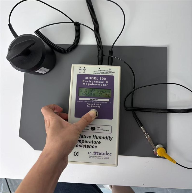
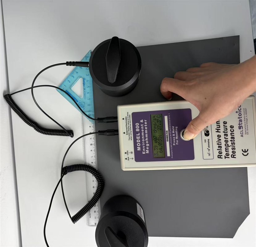

These readings were taken at ambient humidity (about 58–66 %RH), not after the low-humidity conditioning described in ANSI/ESD S4.1. Resistance of dissipative materials rises as humidity falls, so these figures are not a statement of low-humidity performance. The meter displays "ohms/sq", but with external electrodes the value is in ohms. A full test report from an earlier batch is available: PTP test report, 29 July 2026 (PDF). Step-by-step method: how to test an ESD mat.
Which Side of an ESD Mat Goes Up?
The coloured dissipative layer (green, blue or grey) faces up. The black conductive layer faces down, toward the bench, and the ground snap connects into it.
This matters at incoming inspection. If an inspector measures the black bottom layer against a 106–109 Ω window, the mat appears to "fail low". In our tests the bottom layer read 2.50 × 10⁴ to 2.22 × 10⁵ Ω, well below 106 Ω, on mats whose top surfaces were well within range. That low reading is the conductive layer doing its job. Inspection specifications should say which surface is measured, and give the bottom layer its own range or leave it out.
Choosing an ESD Mat: Bench, Floor, Rolls or Cut Sizes
Bench or floor?
For workbenches, use a two-layer dissipative mat with a ground snap. See the ESD bench mat guide for bench-mat sizing and layout. For standing areas and walkways inside an ESD protected area, see ESD floor mats.
2 mm or 3 mm?
2.0 mm suits most assembly, inspection and repair benches. 3.0 mm gives more cushioning and durability for heavy-duty workstations and industrial production.
Roll or cut-to-size?
Rolls (1.2 m × 10, 20 or 30 m) suit long benches and facilities that cut their own lengths. Cut sheets with snaps already fitted save installation time. Tell us the bench length and depth, and we cut to size.
Colour
Green, blue, grey and black are available. Green is the most common bench colour; grey and blue are often chosen for a cleaner look or to match existing fixtures. Colour does not change the electrical specification.
Accessories
Each work position needs a ground snap (10 mm), a ground cord to a common ground point or earth bonding plug, and usually an operator ESD wrist strap connected to the same ground.
How to Ground an ESD Mat
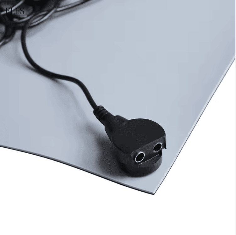
- Fit a ground snap into the mat so that it reaches the conductive bottom layer.
- Connect the ground cord from the snap to a common ground point (CGP), or through an earth bonding plug to the protective earth of the mains supply.
- Connect the operator's wrist strap to the same ground point. Do not ground the wrist strap through the mat.
- Check resistance to ground from the top surface after installation and at regular intervals; it must be below 1 × 10⁹ Ω.
Full guide with photos: how to ground an ESD mat. Grounding hardware: ESD grounding mat and accessories.
What ANSI/ESD S20.20 Requires for Worksurfaces
| Purpose | Test method | Limit |
|---|---|---|
| Product qualification | ANSI/ESD S4.1 | Point to point < 1 × 10⁹ Ω and point to groundable point < 1 × 10⁹ Ω |
| Product qualification (alternative) | ANSI/ESD STM4.2 | < 200 V |
| Compliance verification | ESD TR53 | Resistance to ground < 1 × 10⁹ Ω |
Source: ANSI/ESD S20.20-2014, Table 3. The standard does not require a lower limit. A note in the standard says a lower limit of 1 × 10⁶ Ω should be considered where charged-device-model (CDM) damage is a risk. Our dissipative top layer is designed for 106–109 Ω, which meets both. More background: ANSI/ESD S20.20 requirements and checklist.
Compliance Documents
- RoHS: SGS test report HGFDU26030099786, dated 15 March 2026. The ESD mat sample complies with the limits of RoHS Directive (EU) 2015/863 for lead, mercury, cadmium, hexavalent chromium, PBBs, PBDEs and the four listed phthalates. Download the SGS report (PDF).
- Resistance: in-house ACL Model 800 data above, and the PTP test report (PDF).
- Datasheet: ESD mat datasheet.
Frequently Asked Questions About ESD Mats
Is an anti-static mat the same as an ESD mat?
Often the names are used for the same product. Electrically, what counts is whether the mat is grounded and measures below 1 × 10⁹ Ω point to point and to ground. A mat that only claims to be "anti-static", with no resistance data and no ground connection, is not an ESD mat in the sense of ANSI/ESD S20.20.
How do ESD mats work?
The dissipative top layer slows the discharge from a charged part, and the conductive bottom layer carries the charge across the mat to the ground snap and ground cord. The result is a controlled, slow drain to ground instead of a spark.
What resistance should an ESD mat have?
ANSI/ESD S20.20 requires less than 1 × 10⁹ Ω point to point and to ground. Many users also want at least 1 × 10⁶ Ω on the top surface for CDM-sensitive parts. Our top layer is designed for 106–109 Ω.
Does an ESD mat need to be grounded?
Yes. Without a ground cord connected to a common ground point, the mat has nowhere to send the charge.
Which side of the mat goes up?
The coloured dissipative side faces up. The black conductive side faces down.
Why does the bottom of my mat measure below 106 Ω?
Because it is the conductive layer, designed for 104–106 Ω. Test the top surface for acceptance.
How often should an ESD mat be tested?
Check resistance to ground at installation and then at the interval set in your ESD control plan, using ESD TR53 methods. Many facilities also check after moving or cleaning benches.
How long does an ESD mat last?
It depends on use, cleaning and heat. See how long ESD mats last for the signs that a mat needs replacing.
Request a quote or a sample. Send us the thickness (2 or 3 mm), colour, width and length or cut sizes, quantity, and whether you need ground snaps and cords fitted. We reply with a quote and can send a sample for your own resistance test.
Contact ESDBEST · sales2@esdbest.com
About the author. Rachel Zhong is an ESD engineer at HORBEST Tech Co., Ltd. (ESDBEST), Shenzhen, with 29 years' experience in static-control materials, including worksurface and flooring compounds, test methods and customer incoming-inspection support. Updated 3 November 2026.