How to Test an ESD Mat: Equipment, Method and the Mistake That Causes False Failures
An ESD mat is tested by placing two weighted electrodes on the surface a fixed distance apart and measuring the resistance between them with a megohmmeter. The reading must then be compared against the specification of the layer you are actually measuring — which is where most incoming inspections go wrong.
Quick Summary
- What you need: A megohmmeter rated for surface resistance, plus two weighted electrodes
- Two standard tests: Point-to-point (PTP) and resistance-to-ground (RTG)
- Typical PTP setup: 10 V test voltage, 15 cm electrode spacing
- What to record: The reading, plus temperature and relative humidity
- Most common error: Comparing both layers of a two-layer mat against one resistance range
What Equipment Do You Need to Test an ESD Mat?
You need a megohmmeter capable of measuring into the 10⁹ Ω range, and two weighted electrodes of the type specified for surface resistance measurement.
A standard multimeter is not suitable. Most multimeters top out well below the resistance range an ESD mat operates in, and they apply an uncontrolled test voltage. Surface resistance measurements are voltage-dependent, which is why the test voltage is specified.
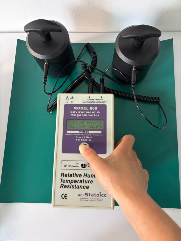
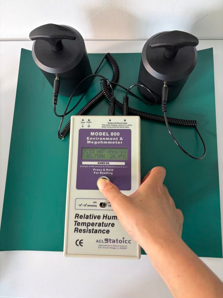
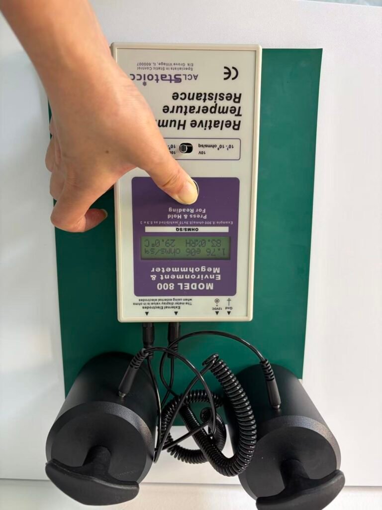
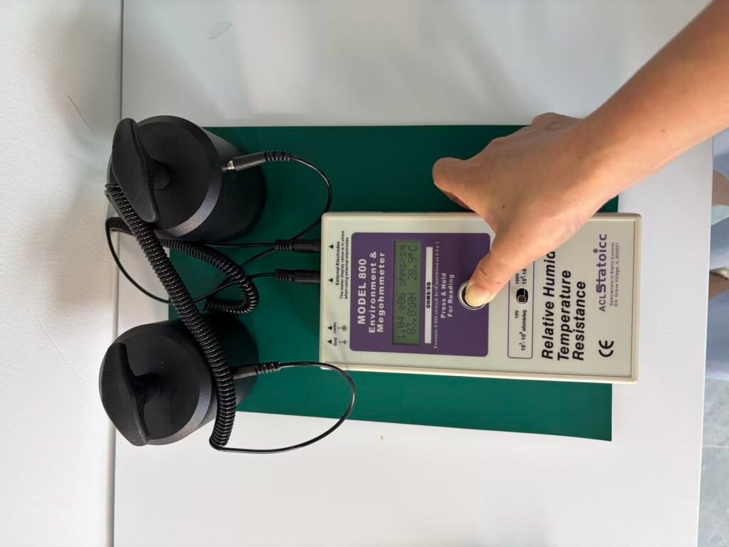
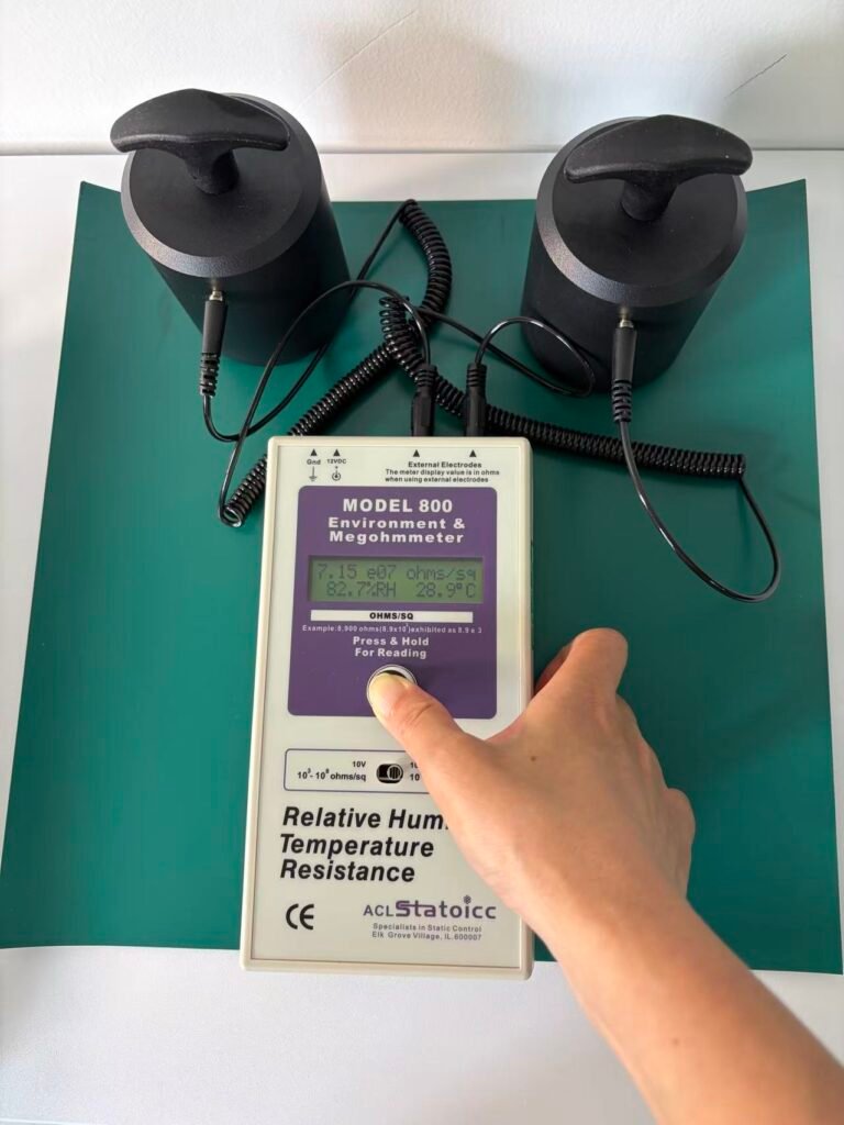
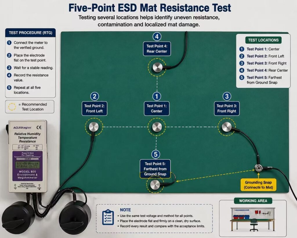
The measurements published on this page were taken with an ACL Staticide Model 800 environment and megohmmeter, which reads resistance and logs temperature and humidity in the same instrument.
How Do You Perform a Point-to-Point Test?
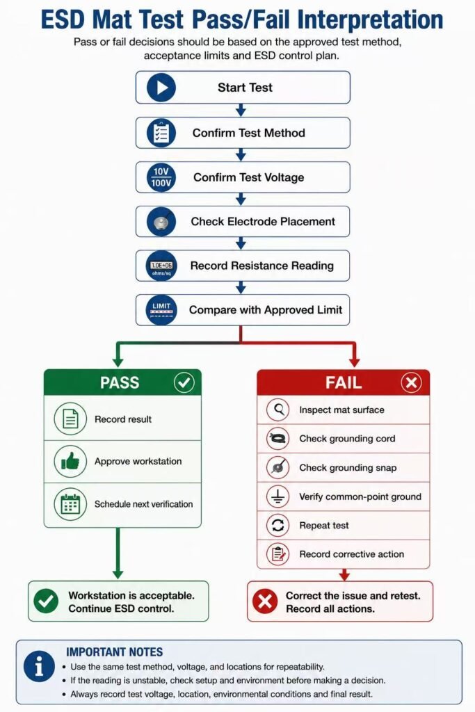
Place two weighted electrodes on the surface being tested, set the spacing, apply the test voltage, and record the stabilised reading.
- Clean the surface and let it stabilise at room conditions.
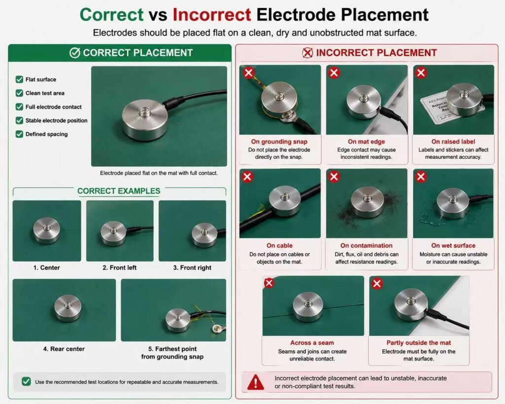
- Place the two weighted electrodes on the layer being tested.
- Set the spacing to 15 cm (150 mm) between electrode edges.
- Select 10 V on the meter.
- Wait for the reading to stabilise, then record it.
- Record temperature and relative humidity at the same time.
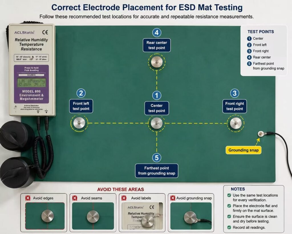
- Repeat at several randomly selected locations across the surface.
Why You Must Record Temperature and Humidity
Surface resistance changes with humidity. A reading taken without recording ambient conditions cannot be meaningfully compared against a reading taken somewhere else.
This is the single most common reason two parties disagree about the same mat. A supplier measures at 40 %RH in an air-conditioned lab, a customer measures at 80 %RH on a factory floor, and the numbers do not match. Neither party is wrong; the test record is incomplete.
Any resistance figure that is quoted without conditions should be treated as an approximate claim, not a measurement.
The Mistake That Causes False Failures at Incoming Inspection
A two-layer mat has two different specifications. Testing the black conductive bottom layer against the 10⁶–10⁹ Ω range specified for the dissipative working surface will produce a “failure” on a mat that is entirely within specification.
The two layers exist to do different jobs:
- Dissipative top layer: 1 × 10⁶ to 1 × 10⁹ Ω — controls the rate of discharge from the working surface
- Conductive bottom layer: 1 × 10⁴ to 1 × 10⁶ Ω — carries charge efficiently to the grounding point
A conductive bottom layer reading 5 × 10⁴ Ω is performing correctly. Compared against the wrong range, it looks like a catastrophic failure. We have seen this cause rejected shipments on conforming product.
Before testing, establish which layer you are measuring and which specification applies to it. See two-layer ESD bench mat construction for how the layers are arranged.
Worked Example: Actual PTP Readings, Layer by Layer
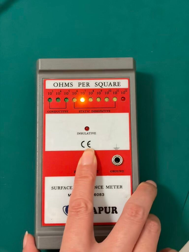
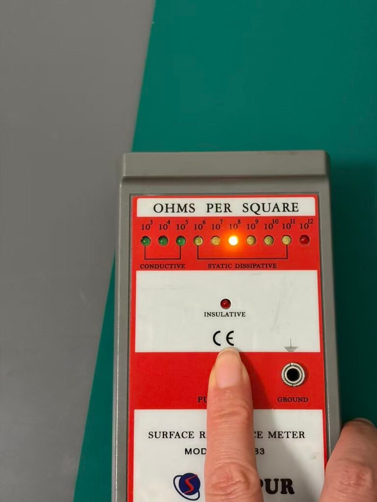
The following are real measurements taken on an ESDBEST two-layer bench mat sample, with each layer evaluated against its own range.
Conditions
- Instrument: ACL Staticide Model 800
- Test voltage: 10 V | Electrode spacing: 15 cm
- Temperature: 29.2–29.4 °C | Relative humidity: 81.7–82.5 %RH
- Sample: 25 × 30 cm, 2.0 mm, two-layer rubber bench mat
- Test date: 29 July 2026 | Operator: Ailon Chen
Green dissipative layer — specification 1 × 10⁶ to 1 × 10⁹ Ω
| ID | Reading | Result |
|---|---|---|
| PTP-T01 | 2.00 × 10⁶ Ω | Within specification |
| PTP-T02 | 2.01 × 10⁶ Ω | Within specification |
Black conductive layer — specification 1 × 10⁴ to 1 × 10⁶ Ω
| ID | Reading | Result |
|---|---|---|
| PTP-B01 | 5.76 × 10⁴ Ω | Within specification |
| PTP-B02 | 3.12 × 10⁵ Ω | Within specification |
| PTP-B03 | 3.12 × 10⁵ Ω | Within specification |
| PTP-B04 | 6.23 × 10⁴ Ω | Within specification |
| PTP-B05 | 6.26 × 10⁴ Ω | Within specification |
| PTP-B06 | 3.50 × 10⁴ Ω | Within specification |
Eight readings, both layers within their respective ranges. Note that a single “8/8 passed 10⁶–10⁹ Ω” statement would be incorrect — six of these readings sit below 10⁶ Ω by design.
A display label that causes confusion
The Model 800’s screen prints “ohms/sq” next to the value. When external electrodes are connected, the displayed figure is in ohms, not ohms per square — the label is fixed and does not change with mode. The note is printed on the instrument itself, beside the external electrode sockets.
This catches people out during incoming inspection. Surface resistivity in ohms/square and point-to-point resistance in ohms are different quantities, and reading the label rather than the instrument note leads to the wrong one being recorded.
Test evidence
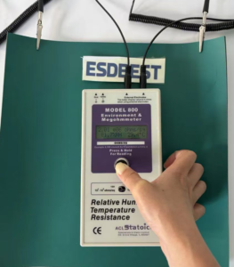
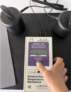
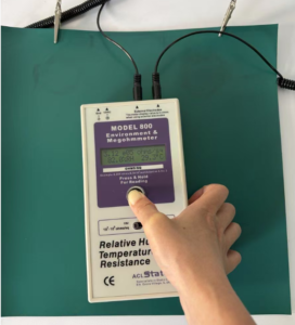
Scope: these values apply to the tested sample under the documented conditions and are not a substitute for lot-by-lot QC records.
How Often Should an ESD Mat Be Tested?
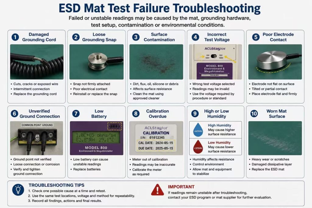
Test on installation, and then at intervals defined by your ESD control programme. Also re-test after any event that could change the surface: a chemical spill, a cleaning process change, or visible wear.
Resistance drifts over time. Contamination, solvent exposure and abrasion all move the reading, and a mat that passed at installation will not necessarily pass two years later. Cleaning is a particularly common cause of drift — see how to clean an ESD mat.
Common Mistakes to Avoid
- Using a multimeter. Wrong range, uncontrolled test voltage.
- Testing both layers against one specification. Produces false failures on conforming product.
- Not recording temperature and humidity. Makes the reading impossible to compare or reproduce.
- Testing one point only. Take readings at several locations across the surface.
- Testing immediately after cleaning. Let the surface dry and stabilise first.
- Inconsistent electrode spacing. Spacing is part of the specification, not a detail.
Frequently Asked Questions
What is an ESD mat tester?
A megohmmeter used with weighted electrodes to measure the surface resistance of a static-control mat.
Can I test an ESD mat with a multimeter?
No. Most multimeters cannot read into the required resistance range and do not apply a controlled test voltage.
What is the difference between point-to-point and resistance-to-ground testing?
Point-to-point measures resistance across the mat surface between two electrodes. Resistance-to-ground measures from the surface to the grounding point, verifying the whole discharge path.
What test voltage should be used?
10 V is commonly used for surface resistance measurements in this range. The voltage should always be recorded with the reading.
What electrode spacing should be used?
The measurements shown on this page use 15 cm (150 mm). Spacing must be consistent across readings that are to be compared.
Why does my mat read 10⁴ Ω instead of 10⁶ Ω?
You are most likely measuring the conductive bottom layer, which is specified at 1 × 10⁴ to 1 × 10⁶ Ω. That reading is correct for that layer.
Does humidity affect ESD mat resistance?
Yes. Surface resistance varies with humidity, which is why ambient conditions must be recorded alongside every reading.
How many points should I test?
Take readings at several randomly selected locations rather than a single point, so that local variation is visible.
My mat passed on installation but fails now. Why?
Resistance drifts with contamination, wear and solvent exposure. Cleaning with industrial alcohol is a frequent cause.
Do I need a calibrated instrument?
For results used in quality records or supplier acceptance, yes. The instrument, its calibration status and the test conditions should all be documented.
Written by Rachel Zhong, HORBEST Tech Co., Ltd. HORBEST has manufactured ESD control products in Shenzhen since 1996, supplying OEM and private-label matting to distributors in Europe, North America, Japan and Southeast Asia. The measurements published on this page were taken in-house. Jinwen Shuzigu, Huangtian, Xixiang, Bao’an, Shenzhen, China. Tel: +86 137 1427 2599