Most explanations of these three categories stop at the definitions. This one includes measured readings taken on a single product — both layers of one two-layer bench mat, tested on an ACL Staticide Model 800, with the temperature and humidity recorded alongside every reading.
The Three Categories in One Sentence Each
All three describe how easily charge moves across or through a material. The difference is only a matter of how much resistance stands in the way.Conductive
Charge moves almost freely. Resistance is low, so a charged object touching a conductive surface loses its charge quickly. In ESD control this is used where fast, reliable charge removal matters more than controlling the speed of the discharge.Static dissipative
Charge still moves, but slowly enough that the discharge is spread out over time rather than happening in one spike. This is the behaviour wanted on a worksurface where sensitive components are handled.Insulative
Charge does not move. It stays where it was generated. Ordinary plastics, cardboard and untreated packaging are insulative, which is why they are kept out of an EPA even when they never touch a component.
On the boundary values: the numeric cut-offs between these categories are set by standards documents and their exact wording has changed between revisions. Check the current text of ANSI/ESD ADV11.2 and ANSI/ESD S20.20 for the figures that apply to your programme rather than relying on a general article — including this one.
Why the Boundaries Are Where They Are
The two ends of the scale fail for opposite reasons, and understanding both explains why the useful range sits in the middle.Too conductive: the discharge happens too fast
Connecting a charged object to ground through near-zero resistance does remove the charge, but it does so almost instantaneously. That produces a current spike, and the spike is itself an ESD event. It can couple into nearby circuitry even when nothing was touched directly. This is the reason wrist strap cords contain a 1 megohm resistor rather than a plain wire.Too insulative: the charge never leaves
At the other end, charge generated by friction simply stays on the surface. A worker moves a plastic tray across a bench, the tray carries a field, and the next component that comes close is exposed to it. Nothing in the process gives the charge anywhere to go.The middle: controlled removal
Static dissipative material removes charge, but over a longer interval. The energy is dissipated gradually instead of released at once. That is the whole design intent, and it is why an ESD worksurface is not simply made as conductive as possible.Measured on a Single Product — Both Layers of One Bench Mat
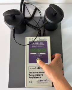
A two-layer bench mat is a useful specimen for this comparison because both categories are present in one piece of material. The green working surface is specified as static dissipative; the black backing layer is specified at a lower resistance. We measured both.
Sample: ESDBEST two-layer rubber ESD bench mat, 25 × 30 cm, 2.0 mm thick
Instrument: ACL Staticide Model 800 environment and megohmmeter
Method: point-to-point (PTP), two external weighted electrodes
Test voltage: 10 V · Electrode spacing: 15 cm (150 mm)
Conditions: 29.2–29.4 °C, 81.7–82.5 %RH
Locations: randomly selected across each surface — 2 on the green layer, 6 on the black layer
Report ID: ESDBEST_PTP_Test_Report_2026-07-29
Green working surface — specified 1×10⁶ to 1×10⁹ Ω
| ID | Measured PTP resistance | Within specified range |
|---|---|---|
| PTP-T01 | 2.00 × 10⁶ Ω | Yes |
| PTP-T02 | 2.01 × 10⁶ Ω | Yes |
Black backing layer — specified 1×10⁴ to 1×10⁶ Ω
| ID | Measured PTP resistance | Within specified range |
|---|---|---|
| PTP-B01 | 5.76 × 10⁴ Ω | Yes |
| PTP-B02 | 3.12 × 10⁵ Ω | Yes |
| PTP-B03 | 3.12 × 10⁵ Ω | Yes |
| PTP-B04 | 6.23 × 10⁴ Ω | Yes |
| PTP-B05 | 6.26 × 10⁴ Ω | Yes |
| PTP-B06 | 3.50 × 10⁴ Ω | Yes |
These readings apply to the sample tested under the conditions recorded above. They should not be generalised to every production lot without the corresponding QC records. Each layer was compared only with its own specified range — not with one universal range covering the whole product.
The Naming Problem Nobody Mentions
Product literature across this industry — ours included — routinely calls a low-resistance backing layer the “conductive layer”. Measured at 10⁴ to 10⁵ ohms, that layer is well above the resistance of an actual conductor, and depending on which standard’s classification you apply, it may fall inside the dissipative band rather than the conductive one. This is a naming convention, not a defect. It describes the layer’s role relative to the working surface above it, which is what matters when assembling a bench. But it causes real confusion during incoming inspection, because an inspector reading “conductive” may test against a conductive-class limit that the product was never designed to meet. The practical rule: compare each measurement against the specification for that specific layer, not against a category name. If a datasheet gives you a category word without a numeric range, ask for the range.Where Each Category Belongs in an EPA
| Location | Typical requirement | Why |
|---|---|---|
| Worksurface | Dissipative | Components rest here; discharge must be slowed, not accelerated |
| Mat backing layer | Low resistance | Carries charge from the working surface to the ground path |
| Flooring | Dissipative or conductive, per programme | Works as a system with footwear; the combined value is what matters |
| Personnel path | Dissipative + 1 MΩ resistor | Operator safety and controlled discharge |
| Packaging entering EPA | Never insulative | Insulative material holds a field even when untouched |