ESD Resistance to Ground Test: Our Workstation Readings, Step by Step
By Rachel Zhong, ESD engineer at ESDBEST, 29 years in static control · Published 18 November 2026
A resistance to ground (RTG) test tells you whether an ESD work surface can drain charge to ground. Most guides give you the limit and leave it there. This page shows a real ESD workstation test from start to finish: our BEN-001 ESD workbench, an ACL 800 megohmmeter, a 5 lb electrode, and photographed readings from three different days. It also covers the set-up mistakes that gave us misleading numbers, and how we found them.
- Limit: ANSI/ESD S20.20 requires a work surface resistance to ground of less than 1 × 10⁹ Ω. Test methods: ANSI/ESD S4.1 to qualify the surface, ESD TR53 to check it in use.
- Ground path first: clip the meter straight onto the metal ground snap. With a typical 1 MΩ ground cord you should read about 106 Ω. Ours read 2.28 – 2.91 × 10⁶ Ω in six checks.
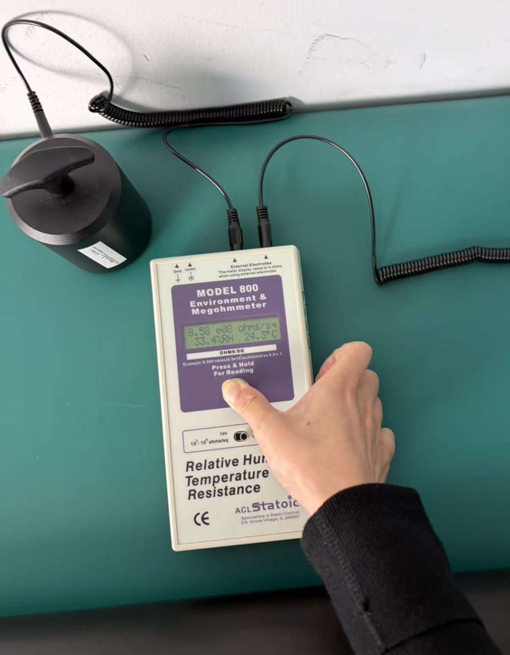
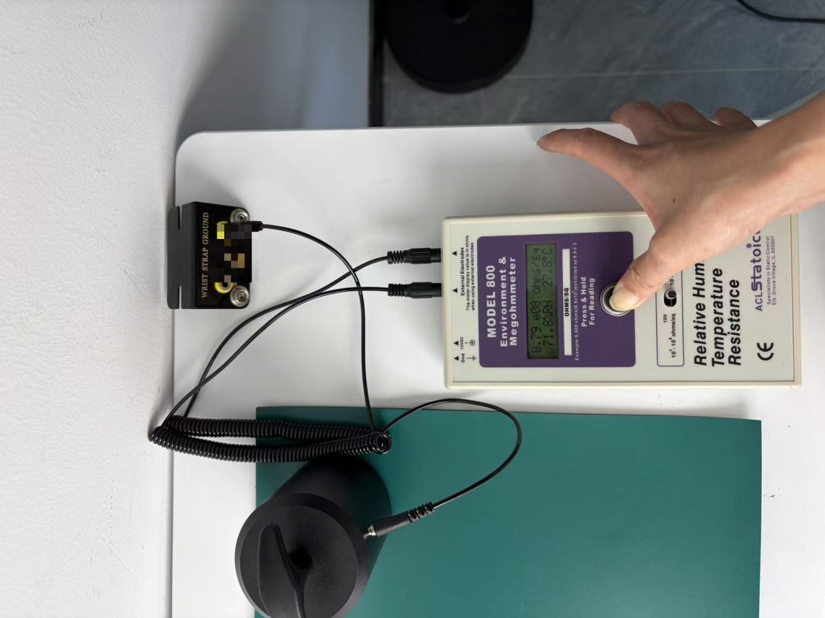
- Then the surface: 5 lb electrode on the mat, lead to the same ground point. Our BEN-001 bench read 8.58 × 10⁸, 8.79 × 10⁸ and 8.75 × 10⁸ Ω, all under 1 × 10⁹ Ω.
- Lesson: 8.8 × 10⁸ Ω passes, but there isn't much margin. Test more than one spot, write down the humidity, and test again in dry weather.
- What is resistance to ground?
- RTG limits for ESD work surfaces
- Equipment we used
- Step 1: check the ground path
- Step 2: measure the work surface
- Our readings
- Readings that look wrong, and why
- Humidity and margin
- RTG vs point-to-point vs Ω/sq
- Five-minute checklist
- FAQ
What is resistance to ground in ESD testing?
Resistance to ground (RTG, also written Rtg) is the resistance measured from a point on an ESD surface to the ground point it is connected to. On an ESD workstation the path is: work surface → mat material → ground snap → ground cord (usually with a 1 MΩ resistor) → common point ground → equipment ground.
Charge on a board placed on the bench has to drain along that whole path. If any link is broken, dirty or too resistive, the surface can still hold a charge, even if the mat itself is fine. That's why the standards test the installed workstation and not just the mat material.
ESD resistance to ground limits for work surfaces
| What | Test method | Limit |
|---|---|---|
| Work surface, product qualification | ANSI/ESD S4.1 resistance to ground and point-to-point | < 1 × 10⁹ Ω |
| Work surface, compliance verification (in use) | ESD TR53 resistance to ground | < 1 × 10⁹ Ω |
| Optional lower limit (CDM concerns) | Note in S20.20 | ≥ 1 × 10⁶ Ω suggested |
| Wrist strap system (for comparison) | Person through strap and cord to ground | < 3.5 × 10⁷ Ω |
Source: ANSI/ESD S20.20-2014, Tables 2 and 3. Your customer's ESD control plan may set tighter limits; if it does, use those.
Equipment we used
- Meter: ACL Staticide Model 800 Environment & Megohmmeter, serial R01172234, calibrated 19 August 2026. It shows resistance, %RH and °C on the same display, so every photo records the conditions.
- Electrode: 5 lb (2.27 kg) cylindrical electrode with a conductive rubber contact, as used for S4.1-style surface tests.
- Test voltage: 10 V. On the ACL 800 the 10 V range covers our readings, and we followed the meter manual's range rules.
- Bench: ESDBEST BEN-001 ESD workbench with its green two-layer rubber ESD mat top (rated 106–109 Ω), mat ground snap, ground cord and wrist-strap ground box.
- A note on the display: the ACL 800 labels its screen "ohms/sq" for the built-in electrodes. With external electrodes plugged in, the manual says the value is in ohms, so every RTG figure below is in Ω.
Step 1: Check the ground path before you touch the mat
Most people skip this step. Before you measure the surface, measure the path the surface depends on. Clip one meter lead directly onto the metal stud of the mat's ground snap and connect the other lead to the ground point. The mat material is now out of the circuit, so the meter sees only the snap, the ground cord and the ground point.
With a standard ground cord that has a 1 MΩ resistor, you should read about 1 × 10⁶ Ω. On 18 November 2026 we repeated this check six times:
| Check | Reading | %RH | °C |
|---|---|---|---|
| 1 | 2.91 × 10⁶ Ω | 72.9 | 28.0 |
| 2 | 2.55 × 10⁶ Ω | 72.8 | 28.2 |
| 3 | 2.32 × 10⁶ Ω | 72.6 | 28.1 |
| 4 | 2.53 × 10⁶ Ω | 72.9 | 28.1 |
| 5 | 2.28 × 10⁶ Ω | 72.6 | 28.1 |
| 6 | 2.30 × 10⁶ Ω | 72.6 | 28.2 |
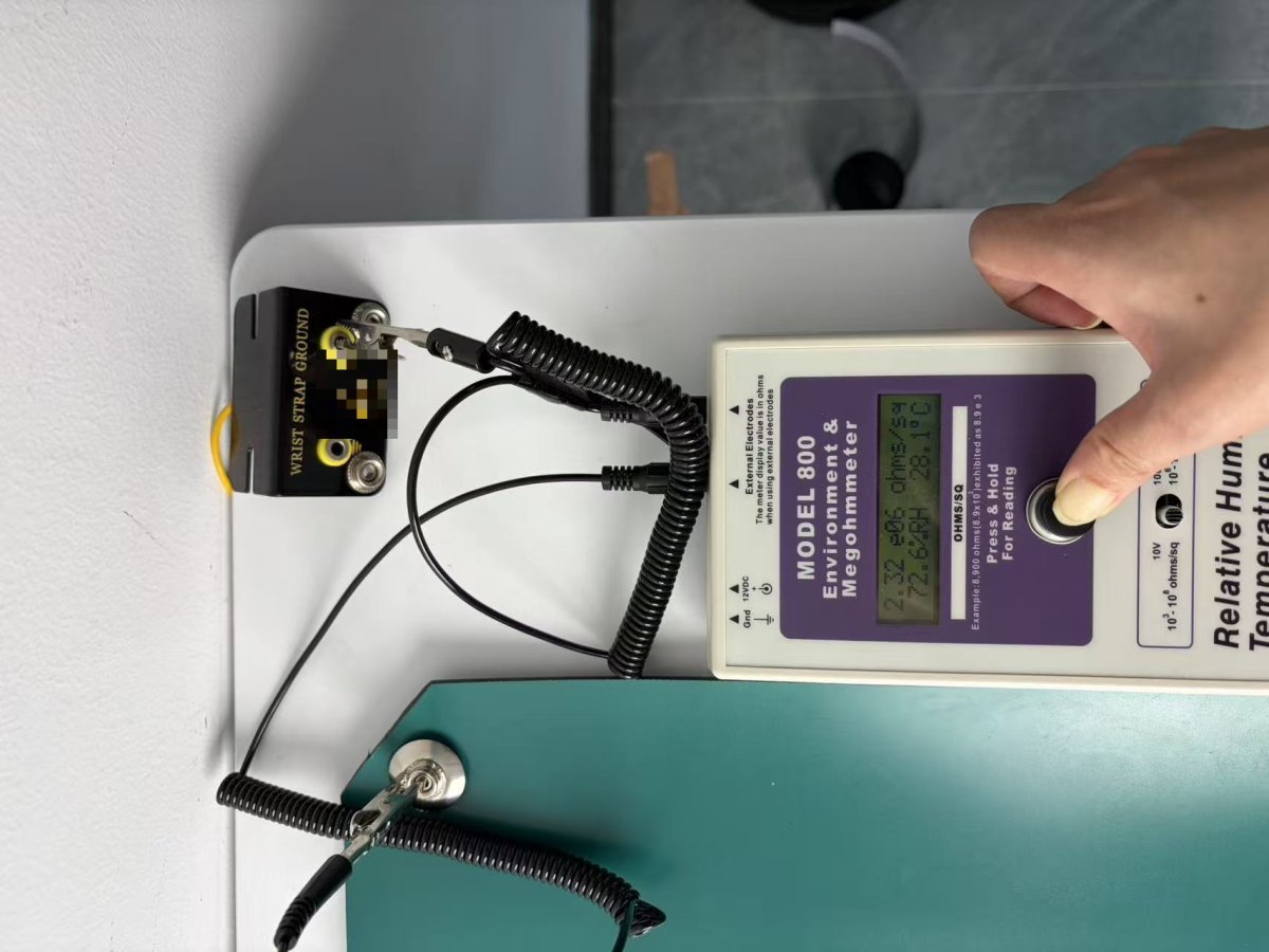
All six readings are within a factor of three of 1 × 10⁶ Ω and close to each other. That's what a healthy cord and ground point look like: the 1 MΩ resistor plus a small contribution from the contacts. If this check reads 108 Ω or higher, or the reading jumps around, stop. The problem is the snap, the cord or the ground point, not the mat, and you won't get a meaningful surface reading until it's fixed.
Step 2: Measure resistance to ground on the work surface
- Clear the test area and wipe it with an ESD-safe surface cleaner. Let it dry.
- Connect the mat ground cord to its ground point, exactly as the bench is used in production.
- Put the 5 lb electrode on the working area of the mat and connect it to the meter.
- Connect the meter's second lead to the same ground point you used in step 1.
- Keep the meter off the surface you are testing (see below), press and hold, and let the reading settle.
- Record the reading, the %RH, the °C, the position and the meter serial number. Take a photo of the display.
Our resistance to ground readings
| Date | Set-up | Reading | %RH | °C |
|---|---|---|---|---|
| 10 Nov 2026 | Electrode on mat → ground point | 8.58 × 10⁸ Ω | 33.4 | 24.3 |
| 17 Nov 2026 | Electrode on mat → ground point, meter resting on the mat | 9.57 × 10⁸ Ω | 71.4 | 28.0 |
| 17 Nov 2026 | Same, meter moved off the mat (1) | 8.79 × 10⁸ Ω | 71.8 | 27.8 |
| 17 Nov 2026 | Same, meter moved off the mat (2) | 8.75 × 10⁸ Ω | 71.7 | 27.8 |
| 18 Nov 2026 | Ground path only (clip on snap → ground point), 6 checks | 2.28 – 2.91 × 10⁶ Ω | 72.6 – 72.9 | 28.0 – 28.2 |
For context, the same bench top read 5.05 × 10⁸ and 5.19 × 10⁸ Ω/sq with the meter's built-in surface electrodes on 9 November (47.3 %RH, 26.9 °C). The ground path adds about 2–3 × 10⁶ Ω, so almost all of the 8.8 × 10⁸ Ω RTG comes from the mat surface. That fits a top layer rated 106–109 Ω.
Readings that look wrong, and what causes them
Some of our early readings were misleading. These are the same mistakes we see in customer audits.
1. The electrode on top of the ground snap reads about 109 Ω, not 106 Ω
Our first "control" reading put the 5 lb electrode on top of the ground snap. It read about 1 × 10⁹ Ω, a thousand times higher than the cord. A flat electrode can't sit on a domed snap: it rests on the snap's plastic cap and on the mat around it, so the current still goes through the mat surface. Clip onto the metal stud instead. Done that way, the same snap read 2.3 × 10⁶ Ω.
2. Readings in the 1012 Ω range
A reading of 1012 Ω or more on an ESD mat almost always means an open circuit somewhere in the path, not a bad mat. Common causes: a clip biting on insulation (a cord boot or wire sheath) instead of metal, the lead in the wrong socket of the ground box, a ground cord that isn't snapped fully home, or an electrode lying across a crease or the mat edge. Check every connection before you blame the mat.
3. Meter resting on the mat
With the meter lying on the mat, our reading was 9.57 × 10⁸ Ω. With the meter moved onto the bare bench, it was 8.79 and 8.75 × 10⁸ Ω, about 8 % lower and very repeatable. The meter case and leads on the test surface can add stray paths. Keep them off it.
Rule of thumb: two matching numbers prove consistency, not correctness. The clip-on ground path check in step 1 is what tells you which path the meter is reading, so do it every time.
Humidity, margin, and why one reading is not enough
The resistance of most ESD materials goes up as the air gets drier, and it varies from spot to spot across a mat. Our readings above, at 33 %RH and at 72 %RH, are only about 12 % below the 1 × 10⁹ Ω limit. With that little margin, a drier day or a different spot on the mat could push a reading over. For that reason:
- Test at several positions: next to the snap, the centre of the working area, and the corner farthest from the snap.
- Always record %RH and temperature with each reading. A reading without conditions can't be compared later.
- Repeat the test in your driest season. Winter mornings with the heating on are the worst case for ESD.
- If your process is sensitive, or your customer wants a bigger margin, choose a work surface with a lower top-layer resistance, in the 106–108 Ω range.
Resistance to ground vs point-to-point vs ohms per square
| Measurement | Path | Unit | What it tells you |
|---|---|---|---|
| Resistance to ground (RTG) | Electrode on surface → ground point | Ω | The installed workstation drains charge to ground |
| Point-to-point (RTT / PTP) | Electrode → electrode on the same surface | Ω | Resistance across the material itself |
| Surface resistivity | Concentric-ring or built-in parallel electrodes | Ω/sq | A material property; not used for the S20.20 work-surface limit |
| Ground path check | Clip on snap → ground point | Ω | Snap, cord and ground point are intact |
A mat can pass point-to-point and still fail RTG if its snap or cord is faulty. A good RTG result also can't make up for a mat that has worn through. Use both. For the full mat procedure, including two-layer mats, see how to test an ESD mat. For the complete bench grounding layout, see ESD workbench grounding.
Five-minute ESD workstation RTG checklist
- Ground path: clip onto the metal snap stud and measure to the ground point. Expect about 106 Ω (1 MΩ cord). If it reads much higher, stop and fix it.
- Clean the test spots with an ESD-safe cleaner and let them dry.
- Measure RTG at three or more positions with the 5 lb electrode, using the same ground point.
- Keep the meter and spare leads off the test surface.
- Record each reading with %RH, °C, position, test voltage and meter serial number, and keep a photo of the display.
- Compare with the limit (< 1 × 10⁹ Ω, or your customer's limit). Also look at the margin. A reading just under the limit needs a dry-season retest.
Need a work surface you can verify? Our BEN-001 ESD workbench (MOQ 1, about one week lead time) and ESD bench mats come with our own measured data. Ask for a quote through our contact page.
FAQ
What is the resistance to ground limit for an ESD work surface?
ANSI/ESD S20.20 requires less than 1 × 10⁹ Ω. Surfaces are qualified with ANSI/ESD S4.1 and checked in use with ESD TR53. Many users also apply a lower limit of 1 × 10⁶ Ω.
How do you test resistance to ground on an ESD mat?
Connect the mat's ground cord as it is used in production. Put a 5 lb electrode on the mat, connect it to a megohmmeter, and connect the meter's other lead to the ground point. Read the value, usually at 10 V, and record it with humidity and temperature. Repeat at several positions.
What should an ESD ground cord measure?
Most mat ground cords have a 1 MΩ resistor, so the cord should read about 1 × 10⁶ Ω. Clipped from the metal snap to the ground point, our cord and ground point read 2.28–2.91 × 10⁶ Ω over six checks.
Why does my RTG reading jump to 1012 Ω?
A reading that high almost always means an open circuit: a lead on insulation instead of metal, a loose snap, a broken cord, or an electrode not sitting flat. Do the clip-on ground path check first.
Can I test resistance to ground with a multimeter?
A multimeter can confirm a ground cord's continuity and its 1 MΩ resistor. It can't verify a dissipative surface, because it doesn't use the standard electrode or test voltage and many models can't read up to 109 Ω.
Is a reading of 8.8 × 10⁸ Ω a pass?
Yes. It is below 1 × 10⁹ Ω. But the margin is small, so record the humidity, test several positions, and retest in dry conditions.
How often should resistance to ground be tested?
Your ESD control plan sets the interval. Many facilities verify work surfaces monthly or quarterly, and again after a bench is moved, repaired or re-matted.